
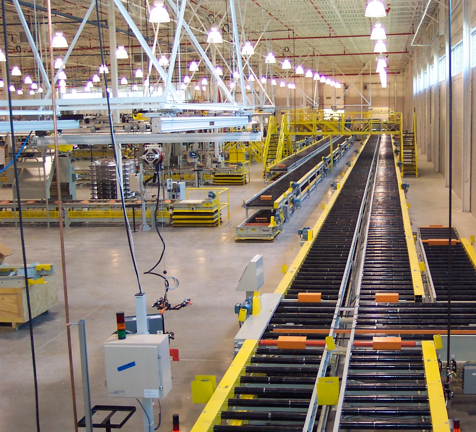
Most AMR transfer station guidance is written around belt conveyors and light-duty roller applications. CDLR operates differently, and those differences have real consequences for how you design the docking interface, the transfer sequence, and the controls logic. If you’re integrating AMRs into a CDLR system, here’s what you need to account for.
Why CDLR Behaves Differently at the Transfer Point
CDLR moves product by driving individual rollers through a continuous chain. That chain runs beneath the roller bed and engages each roller via a sprocket. It’s a robust, high-capacity system well-suited to pallets, heavy totes, drums, and other substantial unit loads that belt conveyors can’t handle reliably.
But that chain drive introduces characteristics that directly affect how an AMR transfer needs to be engineered:
Roller Engagement Is Not Instant
When a CDLR zone is activated, there’s a brief but real ramp-up before the rollers reach full speed. Unlike a belt conveyor, where the surface is either moving or it isn’t, CDLR has a chain engagement sequence. If your transfer logic triggers product release from the AMR the moment the zone activates rather than when it confirms roller speed, you risk product stalling mid-transfer or arriving before the receiving zone is fully ready.
Your PLC logic needs to account for this. A speed confirmation signal or a deliberate delay before the transfer release isn’t over-engineering. It’s the difference between a clean transfer and a jam.
Chain Tension Affects Transfer Consistency
A properly tensioned CDLR chain delivers consistent roller speed and reliable product movement. A chain that’s stretched or under-tensioned doesn’t. In high-cycle AMR applications where transfers happen continuously throughout a shift, chain tension degrades faster than in traditional fixed-schedule operations. The transfer that worked perfectly at startup may behave differently by the end of a long production run.
This is a maintenance reality worth building into your commissioning documentation and your client’s preventive maintenance schedule. It’s also a reason to design some tolerance into your transfer timing rather than assuming the CDLR will always perform at its theoretical specification.
Zone Lengths Are Fixed by Design
CDLR zones are defined by the physical chain circuit and roller configuration. You can’t easily shorten or extend a zone after the system is built. For AMR integration, this matters because your zone length has to accommodate the AMR footprint, the load overhang, and the transfer geometry all at once. Getting zone length wrong at the design stage means either product hanging over zone boundaries during transfer or wasted conveyor real estate that reduces system throughput.
The mechanical design of the CDLR zone and the AMR transfer logic aren’t independent workstreams. The zone length, roller pitch, and chain configuration all need to be defined with the AMR docking geometry in mind from the start.
The AMR Docking Problem on CDLR
AMRs dock with some degree of positional variability every cycle. On a belt conveyor or light-duty roller system, that variability is usually manageable because the load transfer is relatively forgiving. On CDLR handling heavy unit loads, the stakes are higher.
Load Weight Amplifies Docking Errors
A 50-pound tote that transfers slightly off-center is an inconvenience. A 1,200-pound pallet that transfers off-center is a potential jam, a tipped load, or a damaged roller. When you’re designing an AMR transfer station on CDLR, the positional tolerance you build into the docking interface needs to reflect the load weight, not just the robot’s nominal docking accuracy.
In practice this means specifying docking sensors with tighter activation criteria than you might use on a lighter-duty application, and designing the transfer station geometry so that the acceptable docking window aligns with what the AMR can reliably achieve in production, not just in a clean commissioning environment.
The Deck Height Tolerance Stack-Up
On CDLR, the roller surface height is determined by the roller diameter, the frame height, and the mounting configuration. On the AMR side, deck height is a function of the robot model, its load deck design, and any attachment hardware. Getting these to align within a workable tolerance at the transfer point requires both sides to be specced together.
A mismatch of even a quarter inch at the transfer point can cause product to hang up, especially with heavier loads that don’t slide across small height differentials the way lighter product does. Nail down the deck height specification on both sides before you commit to the conveyor frame design. Shimming it out at installation is a solvable problem, but it’s an avoidable one.
Transfer Direction Matters More on CDLR
On CDLR, the chain and roller orientation dictates the direction of product flow. You have one direction of travel per conveyor section. That sounds obvious, but it has real implications for AMR approach angles. The AMR needs to dock in a way that presents the load for transfer in the same direction the rollers drive product. If the AMR’s approach geometry puts the load perpendicular or at an angle to the roller drive direction, you don’t have a transfer station problem. You have a layout problem that needs to be solved at the design stage.
Controls Considerations Specific to CDLR
The PLC logic for a CDLR transfer station shares the same basic structure as any AMR integration, but several CDLR-specific conditions need to be wired into your sequence logic explicitly.
Zone Clear Confirmation
On a standard roller conveyor, a zone clear signal is straightforward. On CDLR handling heavy loads, confirming the zone is truly clear before allowing the AMR to initiate transfer is more critical because the consequences of a false clear are more severe. A heavy pallet arriving into a zone that isn’t fully clear doesn’t just cause a sensor fault. It can damage product, jam the chain, and take the line down.
Design your zone clear logic with appropriate sensor redundancy for the load weights involved. A single photo eye is often sufficient for light-duty applications. For CDLR handling substantial loads, consider confirmation from multiple sensors before the transfer sequence advances.
Speed Confirmation Before Product Release
As noted above, CDLR rollers don’t reach full speed instantly. Your transfer logic should include a speed confirmation step or a defined delay between zone activation and the signal that clears the AMR to release its load. The right timing depends on your specific chain drive configuration and load weight. Establish it during commissioning and lock it into the PLC logic rather than relying on a fixed delay that may not hold up across varying load conditions.
Fault Recovery Has to Be Explicit
CDLR faults, chain jams, roller stalls, drive motor faults, are not self-clearing. When a fault occurs mid-transfer on a CDLR system, your PLC logic needs a defined recovery sequence that holds the AMR at the station, alerts the operator, and prevents the fleet management system from sending another robot into a zone that isn’t ready. If your fault recovery logic isn’t explicit, the most likely outcome is a second AMR arriving at a jammed transfer station and compounding the problem.
Fault recovery logic on CDLR-to-AMR integrations is not optional. Design it before you build it, not after the first production jam.
What to Get Right at the Design Stage
Most CDLR-to-AMR integration problems are design problems, not commissioning problems. They just get discovered at commissioning. Here’s where to focus your attention early:
Define zone length around the AMR, not just the load.
Your CDLR zone needs to accommodate the full AMR footprint during docking, the load dimensions including overhang, and enough clearance at the zone boundaries to allow the transfer to complete cleanly. Design the zone length with these constraints as inputs, then work back to the chain circuit configuration.
Specify deck height on both sides simultaneously.
Get the CDLR frame height and roller spec locked in alongside the AMR deck height and attachment design. These need to be solved together. If your mechanical and robotics teams are working these independently, close that gap before any fabrication starts.
Build chain maintenance into the commissioning handoff.
Chain tension, lubrication intervals, and wear indicators should be documented and handed off to the end user as part of commissioning, not buried in a generic maintenance manual. In high-cycle AMR applications, CDLR chain maintenance intervals are shorter than most clients expect. Set that expectation early.
Validate with actual loads at actual cycle rates.
Light-load testing during commissioning will not reveal the transfer timing issues, deck height sensitivities, or zone clear timing problems that show up under production conditions. Test with the heaviest load the system will handle, at the throughput rate the client expects to run, before you sign off.
Confirm AMR docking tolerance against CDLR transfer geometry.
Take the AMR manufacturer’s published docking accuracy spec and test it in your actual environment before you finalize transfer station geometry. Published specs are measured under ideal conditions. Production environments are not ideal. Design your transfer station around the docking performance you can actually achieve, with appropriate margin.
Design the CDLR Transfer Station Right the First Time
CDLR is the right technology for a lot of heavy unit load applications that AMR-integrated systems need to handle. But it requires more deliberate design at the transfer point than lighter-duty conveyor types. The chain drive characteristics, the zone geometry constraints, and the load weight involved all raise the stakes on decisions that might be lower-risk in a belt or light-roller application.
Power Pack has been engineering CDLR systems for demanding industrial applications since 1929, and we’ve been integrating them with mobile robotics platforms as AMR adoption has grown across the industries we serve. If you’re working through a CDLR-to-AMR application and want to pressure-test your transfer station design before you commit to it, give us a call and we’re glad to get into the specifics with you.
